Rigging

Today's lesson we started from creating a basic tentacle model. We made a cube and form it into a longer object so we could place a few joints inside. We created 3 joints.
To create joints we had to make sure we are in Rigging mode. In Skeleton we selected Create Joints, then from the bottom to top created 3 joints.
The next step was to select all joints and the object and in options, select Skin then Bind Skin and Reset Settings then just press Bind Skin.

To see through the object I selected Shading then X-Ray Joints.
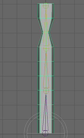
The next step was to create 3 circles. Each of the circles has a different size. The smallest one on the top and the biggest on the bottom. To snap circle to the joint I selected V + Middle Mouse + Right Click on the joint. After I assigned all circles to the joint I Freeze Transformations (Modify) for each circle.

To assign joints with the circle I started from the bottom circle. In outliner settings, I drag and drop joints under the bottom circle. Then I moved to the middle circle and I selected the middle and top joints. In settings, I clicked on Constrain - Orient - Reset Settings - Maintain Offset - Add. I did the same procedure with the top circle and the top joint. In the last step, I drag and drop (Outliner) middle and top circle under the bottom circle.

Expression

With selected top and middle circle, in Attributes Editor - Transform Attributes I right-clicked in Rotate window and select Create New Expression. I added X and Z rotations.
Tentacle Mash
To create multiple objects I selected the current object, then MASH and clicked on the first icon under the Curves/Surfaces. In MASH Distribute I changed the number to 10 and in Distribute Type I selected Mesh. The next step I created a sphere. I dragged Sphere from Outliner and drop it in Input Mesh in MASH Distribute window. The objects I created at the beginning assigned to the sphere.
In Outliner I selected MASH and Add Time Node. I clicked on Sphere + Shift + click on the MASH_ReproMesh. I went to Edit, Group Options, Reset Settings and Group. I created a new MASH. In MASH Distribute I select Spherical in Distribute Type. In Random, I played with the settings to place objects around the scene.


Rigging Control Robot
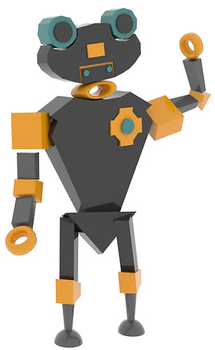
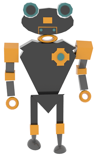
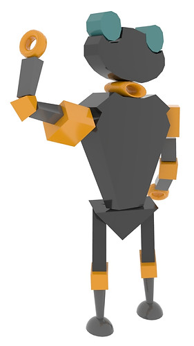
Using all the methods we learned so far, our first formal assignment is to create a rigging control robot. In Maya, I build a robot and began the process of adding joints, IKHandles and controllers.
Here are a few renders of my final project.
After I build the main body I moved from Modelling mode Rigging where I started from creating a joint.
First of all, I did the arms joints and legs. I snapped the joint to the centre pivot of the object. Then I added the spine joints. When I tested the robot movements of the arms and legs I decided to change the joint for IKHandle joints. It works better and gives a more natural look. To be sure the IKHandle would work properly I slightly move the elbow to give it the right angle. Before I IKHandle I clicked on the joints and use the Orient to place them all in the right direction.


To snap joint to the objects, I had to turn on the Local Rotation Axes to see where is the pivot. Then I clicked V + middle mouse and drag and drop joint to the pivot.

Joints snapped to object pivot
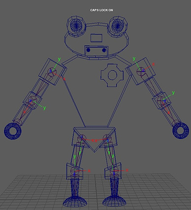

IKHandle and controllers

Setting Driven Keys


In the beginning, I created the Circle Nurb, scale it up, snap to the middle joint (hips). Then I Freeze Transformation, select the Nurb + joint + Constraint + Parent. Now the circle controls the robot so when I move it up and down the body follows. To add extra attributes I switched from Rigging to Animation mode than in that Circle Nurb settings I select Attributes + Add Attributes. I named all the attributes one by one and add min and max Numeric Attribute Properties. I set the key and the movement so I could control the robot from the Channel Box.
The process might look simple and easy, but it actually takes time. One mistake can cost the rig not to work properly. At the final stage of the project, I animated the robot and render the outcome.
Final Renders
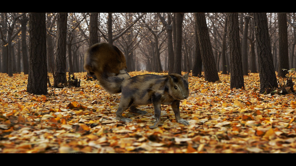
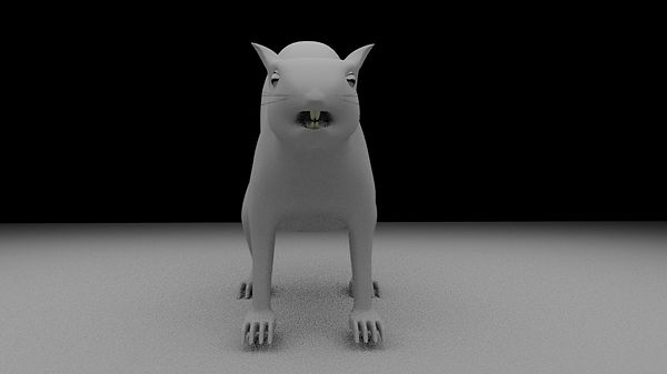
For this final assignment, I am going to use the squirrel I model for the 3D Match Moving. I think it will be perfect for this assignment as I want to add fur to this model. I will also create joints, so it could walk around the Maya scene.
Reference Image

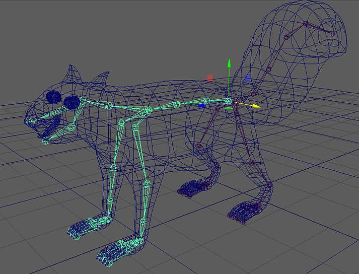
I will also create a skeleton for the squirrel and make it walks around the assignment scene. I made the moving eyelids and open mouth so the squirrel will also blink and open and close mouth.


Renders without fur


Eyelids
I am currently working on joints and controls. The next step will be adding fur.


When I tried to add fur I had an error and I don't know how to fix it. I google out the error and tried the recommended method to fix it, but none of them works.
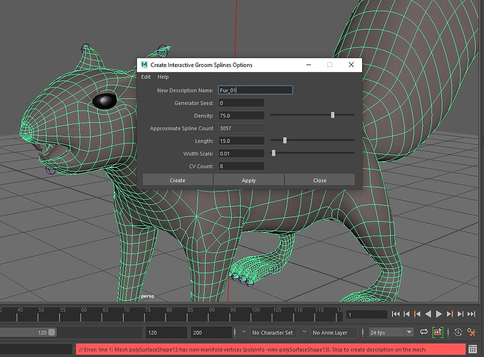
I managed to fix the issue with teacher help. The reason why I couldn't create the Groom was hidden faces inside the model. I deleted all the spare faces and it allowed me to create the Groom. I am currently working on it.
UV

XGen

Fur


List of the brushes I used so far. I am going to add more hair to tail to make it looks fluffy.
I continued working on the fur. There are few spots with missing fur, but it is hard to work around that area because there are many small faces and it is difficult to draw a perfect mask in Photoshop.
Clump
Fur texture


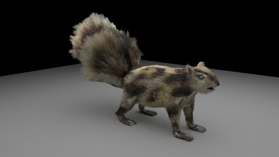
The final outcome for XGen. At the very end, I added two layers of a clump to give the fur the natural look. I also added noise but lower it to a minimum.


Background

Final Outcome
Unfortunately, I wasn't able to animate my original project because the XGen fur didn't follow the squirrel body. I didn't find a solution to that problem. I kept the project hoping I could go back to it next year and find a way to fix it. I had to make a new project.